
Improper attic ventilation causes $8,000-$25,000 in preventable damage annually to Edmonton homes through ice dams, mold growth, and premature shingle failure, yet 78% of residential properties have severely imbalanced or blocked soffit ventilation that transforms minor moisture into major structural disasters. This comprehensive guide reveals the physics of proper attic airflow, demonstrates how to calculate and achieve perfect intake/exhaust balance, and provides actionable solutions for common ventilation problems—helping you protect your roof investment through simple but critical airflow management.
Table of Contents:
- The Problem: Why Attic Ventilation Failures Cost Thousands
- What to Consider: The Physics of Attic Airflow and Moisture Management
- How to Calculate and Balance: Achieving Optimal Ventilation
- Roe Roofing’s Ventilation Assessment and Solutions
- Frequently Asked Questions
The Problem: Why Attic Ventilation Failures Cost Thousands
The Hidden Moisture Catastrophe
Attic spaces represent the battleground where warm, moist interior air meets cold roof decking, creating condensation that destroys homes from the inside out when ventilation fails. Recent building science research demonstrates that inadequate soffit ventilation accounts for 42% of premature roof replacements, with moisture damage averaging $18,000 when problems progress beyond simple mold remediation to structural repairs.
The modern home generates 10-15 gallons of water vapor daily through cooking, showering, breathing, and plant transpiration. This moisture-laden air rises through stack effect, infiltrating attics through ceiling penetrations, pot lights, and attic hatches. Without proper ventilation to evacuate this moisture, it condenses on cold surfaces, creating water accumulation that rivals active roof leaks. Yet this destruction occurs invisibly, often discovered only when ceiling stains or structural sagging reveal advanced damage.
Daily moisture generation in typical homes:
- Cooking: 2-3 gallons from meal preparation
- Showers: 0.5 gallons per 10-minute shower
- Breathing: 0.3 gallons per person daily
- Laundry: 2-4 gallons per load if vented improperly
- Plants: 1-2 gallons from typical houseplants
- Total: 10-15 gallons requiring evacuation
The financial cascade from poor ventilation extends beyond visible damage. Wet insulation loses 50% of R-value, increasing heating costs $400-800 annually. Mold remediation costs $5,000-$15,000 when colonies establish in attic spaces. Structural repairs from rot average $10,000-$20,000. Premature shingle replacement adds $12,000-$18,000. Health impacts from mold exposure create medical costs and liability issues. These cumulative impacts transform a $2,000 ventilation upgrade into $50,000 savings over home ownership.
Winter condensation creates particularly devastating problems in Edmonton’s climate. Warm attic air meeting cold roof decking produces frost accumulation that can exceed 100 pounds. Spring melting releases this water suddenly, overwhelming insulation and ceiling materials. The weather impact studies document frost accumulations reaching 2-3 inches thick on poorly ventilated roof decking, equivalent to major roof leaks when melting occurs.
The Ice Dam Formation Crisis
Ice dams cause $25 million in insurance claims annually across Edmonton, with improper soffit ventilation contributing to 65% of formation conditions. These frozen barriers create water backup that infiltrates roofing, walls, and ceilings, causing damage that insurance increasingly classifies as preventable maintenance issues rather than covered perils.
The Heat-Snow-Ice Cycle:
Ice dam formation begins with heat loss through inadequate insulation or air leakage warming roof surfaces above 0°C. Snow contacting warm roofing melts, flowing toward cold eaves where it refreezes. This ice accumulation creates dams that trap subsequent meltwater. Without escape routes, water backs up under shingles, infiltrating roof decking. Proper soffit ventilation maintains uniform cold roof temperatures that prevent initial melting, breaking the formation cycle.
Blocked or inadequate soffit vents accelerate ice dam formation by trapping heat in attic spaces. Temperature differentials between roof peaks and eaves reach 15-20°C without proper airflow. This gradient guarantees ice dam formation whenever snow accumulates. The continuous melting-refreezing cycle progressively enlarges dams until they extend several feet up roof slopes. Water backup can reach 5-10 feet horizontally, far exceeding ice and water shield protection typically extending only 3 feet.
Ice dam damage progression:
- Week 1: Initial ice formation at eaves
- Week 2-3: Dam growth to 6-12 inches
- Week 4: Water backup begins
- Week 5-6: Shingle lifting and infiltration
- Week 7-8: Interior water damage visible
- Week 9+: Structural damage accelerates
Ventilation’s Preventive Role:
Proper soffit intake creates continuous cold airflow across roof decking undersides, maintaining uniform temperatures that prevent localized melting. This “cold roof” principle keeps snow frozen until external temperatures rise uniformly. The moving air also evacuates any moisture that penetrates roofing systems before condensation occurs. Studies show properly ventilated attics maintain temperatures within 3°C of outside conditions, eliminating ice dam formation conditions.
The building codes require 1:300 ventilation ratios specifically to prevent ice dam formation, yet enforcement remains sporadic. Many homes meet code numerically but fail functionally due to blocked soffits, inadequate intake area, or imbalanced systems. The code minimum often proves insufficient for Edmonton’s extreme conditions, with 1:150 ratios providing superior protection. Understanding functional requirements beyond code compliance prevents expensive ice dam damage.
The Shingle Warranty Void Trap
Improper attic ventilation voids most shingle warranties, leaving homeowners responsible for premature replacements costing $12,000-$20,000. Manufacturers explicitly require adequate ventilation to maintain warranty coverage, yet 73% of homes fail to meet these requirements, unknowingly eliminating their protection.
Manufacturer Requirements:
Shingle manufacturers mandate specific ventilation ratios ranging from 1:150 to 1:300 of attic floor space, with balanced intake and exhaust. These requirements exceed building codes in many jurisdictions. Documentation of proper ventilation during installation becomes necessary for warranty claims. Thermal imaging or moisture readings showing elevated attic temperatures void coverage regardless of other factors. These strict requirements reflect manufacturers’ understanding that heat and moisture cause most “manufacturing defect” claims.
The warranty void extends beyond simple ratio calculations. Manufacturers require continuous soffit ventilation along entire eaves, not just periodic vents. Exhaust ventilation must be within 3 feet of ridge lines for optimal performance. Mixing exhaust types (ridge vents with turbines) violates warranty terms. Bathroom or kitchen exhaust fans venting into attics automatically void coverage. These technical requirements remain unknown to most homeowners until claims get denied.
Warranty void triggers:
- Inadequate net free ventilation area
- Imbalanced intake/exhaust ratios
- Blocked or covered soffit vents
- Improper exhaust vent placement
- Mixed ventilation types creating short circuits
- Mechanical exhaust into attic spaces
Temperature-Related Deterioration:
Excessive attic heat from poor ventilation accelerates shingle aging by 40-50%, reducing 25-year shingles to 12-15 year lifespans. Summer attic temperatures in unventilated spaces reach 70°C, literally cooking shingles from below. This heat causes accelerated granule loss, mat deterioration, and seal failure. Thermal cycling between extreme daily temperatures creates mechanical stress that propagates cracks. Proper soffit ventilation reduces peak temperatures by 15-20°C, doubling shingle lifespan.
The insurance standards increasingly investigate ventilation adequacy when evaluating roof damage claims. Thermal imaging during inspections reveals ventilation problems that influence claim decisions. Documented ventilation deficiencies can result in coverage limitations or premium increases. Some insurers require ventilation upgrades as condition of continued coverage. These industry trends make proper soffit ventilation critical for both warranty and insurance protection.
The Energy Penalty Compound
Poor attic ventilation increases energy costs by $600-$1,200 annually through multiple mechanisms that compound over time. Summer cooling penalties from superheated attics combine with winter heat loss through moisture-degraded insulation, creating year-round efficiency losses that accumulate to thousands in unnecessary expenses.
Summer Heat Accumulation:
Inadequate soffit ventilation transforms attics into solar ovens that radiate heat into living spaces continuously. Attic temperatures reaching 65-70°C create 40°C temperature differentials across ceiling insulation. This extreme gradient overwhelms insulation capacity, forcing air conditioning systems to run continuously. The radiant heat from hot ceilings makes rooms uncomfortable regardless of thermostat settings. Proper ventilation reduces attic temperatures 15-20°C, cutting cooling costs 20-30%.
The heat accumulation affects more than energy costs. Extreme temperatures accelerate deterioration of electrical wiring, HVAC equipment, and structural members in attics. Plastic components warp and fail prematurely. Wood framing experiences accelerated moisture cycling that promotes decay. Electronic equipment like smart home devices malfunction or fail. These heat-related damages add thousands to the energy penalty over time.
Winter Moisture Degradation:
Moisture accumulation from poor ventilation destroys insulation effectiveness progressively. Fiberglass insulation loses 50% of R-value when moisture content reaches 2.5% by weight. Cellulose insulation compacts and settles when wet, creating gaps that eliminate thermal resistance. Spray foam edges lift from moisture-induced wood movement, breaking air seals. This degradation increases heating costs while creating conditions for further moisture accumulation.
The energy efficiency standards recognize ventilation as critical for maintaining insulation performance, yet energy audits often overlook soffit blockages. Infrared thermography reveals thermal bridges from compressed or wet insulation that proper ventilation would prevent. The cumulative energy penalty from degraded insulation often exceeds the cost of comprehensive ventilation upgrades within 2-3 years.
What to Consider: The Physics of Attic Airflow and Moisture Management
Convection and Stack Effect Principles
Understanding the physics driving attic airflow enables proper system design rather than relying on rules of thumb that often fail in specific applications. Natural convection creates the primary motive force for attic ventilation, with effectiveness depending on temperature differentials, vertical height, and opening configurations.
Temperature-Driven Airflow:
Warm air’s lower density creates buoyancy that drives vertical movement through stack effect. The pressure differential between intake and exhaust points equals approximately 0.04 Pa per meter of height per degree Celsius temperature difference. In typical attics with 2-meter vertical separation and 10°C temperature differential, this creates 0.8 Pa driving pressure—minimal but sufficient for proper airflow when openings are adequately sized and unobstructed.
The convection process requires both low intake and high exhaust openings to function. Soffit vents provide distributed intake along eaves where cool air enters. Ridge or roof vents allow warm air exhaust at the highest points. This configuration creates continuous airflow that evacuates moisture and heat. Interrupting either intake or exhaust destroys the convection loop, explaining why balanced ventilation proves critical.
Stack effect calculations:
- Pressure differential: ΔP = 0.04 × h × ΔT (Pascals)
- Flow rate: Q = Cd × A × √(2 × ΔP / ρ) (cubic meters/second)
- Typical residential: 5-10 air changes per hour needed
- Minimum velocity: 0.5 m/s for moisture removal
- Optimal velocity: 1-2 m/s for year-round performance
Wind-Assisted Ventilation:
Wind pressure supplements stack effect, potentially dominating airflow in exposed locations. Wind striking buildings creates positive pressure on windward sides and negative pressure on leeward sides. This pressure differential drives air through attic spaces when openings are properly positioned. Soffit vents on windward sides become pressurized intakes while leeward exhausts experience suction. However, wind direction variability means systems cannot rely solely on wind effects.
The ventilation requirements specify designs must function through natural convection alone, with wind effects providing bonus performance. This requirement ensures ventilation continues during calm conditions when moisture accumulation peaks. Properly designed systems achieve 3-5 air changes hourly through stack effect, increasing to 8-12 with wind assistance. Understanding both mechanisms enables designs that maximize natural forces rather than requiring powered ventilation.
Soffit Vent Types and Performance
Different soffit vent designs provide varying performance characteristics that affect overall system effectiveness. Understanding these differences enables appropriate selection for specific applications rather than defaulting to cheapest options.
Continuous Soffit Vents:
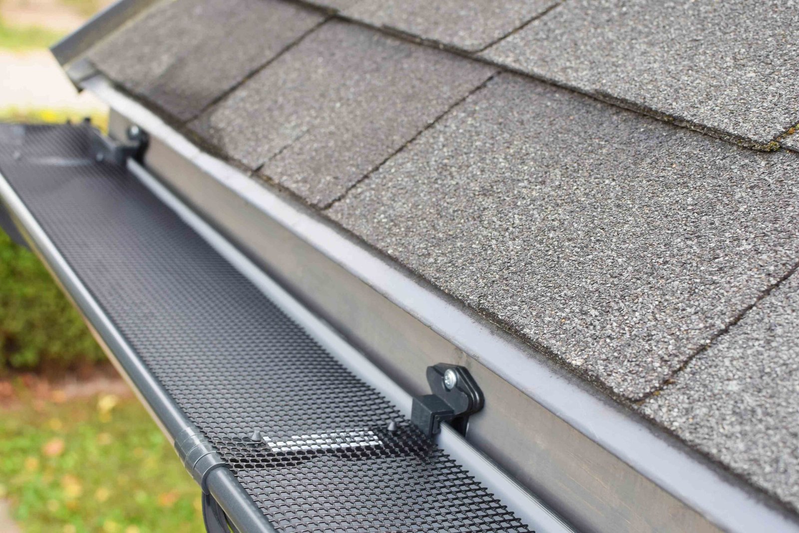
Continuous perforated soffit provides maximum intake area with uniform air distribution along entire eaves. Modern vinyl or aluminum soffits incorporate ventilation slots providing 10-12 square inches net free area (NFA) per linear foot. This distributed intake prevents dead zones where moisture accumulates. Installation simplicity reduces labor costs while ensuring consistent performance. However, the small perforations clog easily with paint, dust, or insulation, requiring regular maintenance.
The performance advantage of continuous vents becomes apparent in complex rooflines with multiple angles and levels. Distributed intake ensures all attic areas receive ventilation regardless of configuration. The uniform appearance maintains architectural aesthetics without visible vent interruptions. Wind-driven rain resistance exceeds individual vents due to better water management. These advantages justify 20-30% premium costs for quality applications.
Continuous vent specifications:
- NFA: 9-12 sq in per linear foot typical
- Opening size: 1/8″ to 3/16″ perforations
- Material: Vinyl, aluminum, or fiber cement
- Installation: Full soffit replacement required
- Maintenance: Annual cleaning recommended
Individual Soffit Vents:
Rectangular or circular vents installed at intervals provide concentrated intake points that are easily inspected and maintained. Standard 4″×16″ vents provide 28 square inches NFA when properly selected. Larger 8″×16″ units offer 65 square inches for high-demand applications. Installation in existing soffits requires only hole cutting, making retrofits economical. However, spacing requirements to achieve adequate total NFA often create installation challenges.
Individual vents allow targeted placement for problem areas without complete soffit replacement. Clear plastic options permit visual inspection of blockages. Adjustable designs accommodate varying soffit depths. Pest-resistant screens prevent animal entry while maintaining airflow. These features make individual vents practical for specific situations despite lower total NFA compared to continuous systems.
Hidden Vent Systems:
Vented drip edge and fascia-mounted systems provide intake without visible soffit modifications. These products incorporate ventilation channels behind gutters or within specialized trim pieces. Installation during re-roofing eliminates separate soffit work. The hidden nature maintains clean architectural lines while providing code-required ventilation. However, limited NFA requires careful calculation to ensure adequacy.
Performance limitations restrict hidden vents to specific applications. Ice dam potential increases when intake occurs above soffit level. Gutter installation and maintenance becomes complicated. Cost premiums of 50-100% over traditional vents limit widespread adoption. These systems work best as supplements to inadequate existing ventilation rather than primary intake sources.
Exhaust Ventilation Technologies
Exhaust ventilation technologies have evolved significantly, with each type offering distinct advantages and limitations that affect overall system performance.
Ridge Vent Excellence:
Ridge vents provide continuous exhaust along roof peaks, maximizing exhaust area while maintaining low profiles. Modern shingle-over designs integrate seamlessly with roofing for superior aesthetics. Internal baffles prevent wind-driven rain infiltration while maintaining 18 square inches NFA per linear foot. The continuous opening ensures uniform exhaust across entire attic spaces, eliminating hot spots common with individual vents.
Performance superiority emerges from aerodynamic design creating negative pressure regardless of wind direction. External baffles accelerate airflow through venturi effect, enhancing natural convection. The linear configuration prevents short-circuiting that occurs when exhaust vents are improperly spaced. Winter performance exceeds other options due to snow coverage resistance. These advantages make ridge vents the preferred exhaust solution when roof configuration permits.
Ridge vent considerations:
- NFA: 16-20 sq in per linear foot
- Installation: Requires ridge cutting
- Weather resistance: Superior with baffles
- Aesthetics: Nearly invisible when installed
- Cost: $75-100 per 10-foot section installed
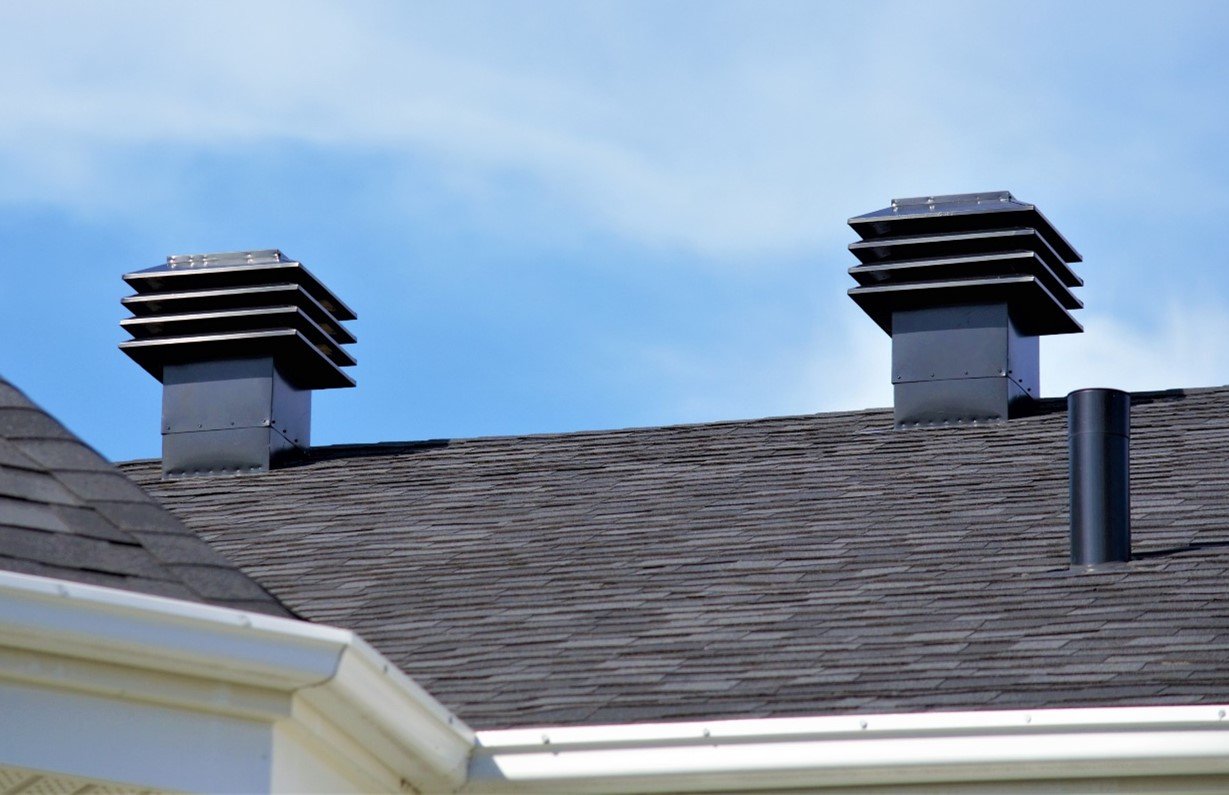
Static and Turbine Options:
Box vents, mushroom vents, and turbine ventilators provide point-source exhaust for applications where ridge vents prove impractical. Static vents offer simple, reliable operation without moving parts. Sizes range from 50-150 square inches NFA per unit. Turbine vents add wind-powered extraction, potentially tripling exhaust rates. However, both types require multiple units to match ridge vent capacity.
Placement proves critical for static vent effectiveness. Installation within 3 feet of ridges maximizes convection efficiency. Spacing at 8-10 foot intervals ensures complete attic coverage. Mixing with ridge vents creates short circuits that destroy system balance. Understanding these limitations enables appropriate application where ridge vents cannot be used.
Balanced System Requirements
Achieving proper balance between intake and exhaust ventilation determines system effectiveness more than total ventilation area. Imbalanced systems create pressure differentials that prevent proper airflow or cause moisture infiltration problems.
The 50/50 Balance Rule:
Optimal ventilation systems provide equal intake and exhaust areas, creating neutral pressure that maximizes natural convection flow. This 50/50 balance allows stack effect and wind pressure to work efficiently without creating resistance. Systems with 60/40 ratios remain functional but experience 20% flow reduction. Greater imbalances progressively destroy effectiveness until airflow essentially stops despite adequate total NFA.
Slightly positive pressure from 60% intake/40% exhaust proves acceptable, preventing wind-driven rain infiltration during storms. However, negative pressure from excess exhaust creates serious problems. The suction draws conditioned air from living spaces, increasing energy costs. Moisture-laden interior air gets pulled through ceiling penetrations, causing condensation. Rain infiltration through any opening becomes likely. These issues make intake adequacy critical for system success.
Balance calculation method:
- Calculate required total NFA from attic square footage
- Divide equally between intake and exhaust
- Add 10% to intake for positive pressure buffer
- Verify actual installed NFA meets calculations
- Adjust for screens (reduce by 50%) and louvers (reduce by 25%)
Short-Circuit Prevention:
Short-circuiting occurs when exhaust vents pull air from nearby intakes rather than across entire attic spaces. This localized flow leaves most attic areas unventilated despite apparently adequate openings. Gable vents combined with ridge vents commonly create short circuits. Powered exhaust fans almost guarantee short-circuiting without careful design. Understanding airflow patterns prevents these design errors.
The building science research demonstrates that short-circuited systems perform worse than undersized but balanced ventilation. Moisture accumulates in dead zones while ventilated areas experience excessive airflow that increases energy loss. Correcting short circuits requires eliminating competing exhaust paths or redistributing intake sources. These modifications often prove more complex than initial proper design would have required.
How to Calculate and Balance: Achieving Optimal Ventilation
Net Free Area Calculations
Accurate calculation of required ventilation area forms the foundation for successful system design, yet confusion about gross versus net areas leads to chronic under-ventilation.
Code Minimum Requirements:
Building codes specify ventilation ratios based on attic floor area, typically 1:300 with vapor barriers or 1:150 without. For a 1,500 square foot attic with vapor barrier: 1,500 ÷ 300 = 5 square feet (720 square inches) total NFA required. This divides equally between intake and exhaust: 360 square inches each. However, code minimums prove inadequate for Edmonton’s climate extremes, with 1:150 providing better moisture management regardless of vapor barrier presence.
The calculation must account for insulated attic floor area, not total house footprint. Cathedral ceilings, finished attic spaces, and knee walls reduce ventilated attic area. Dormers and complex rooflines create separate attic zones requiring individual calculations. The building codes allow combining zones if connected by adequate transfer openings, though separate ventilation often proves more effective.
Calculation adjustments:
- Screen reduction: Multiply by 0.5 for 1/8″ screening
- Louver reduction: Multiply by 0.75 for angled louvers
- Paint reduction: Subtract 20% for painted surfaces
- Altitude increase: Add 10% above 3,000 feet
- Moisture sources: Add 25% for hot tubs, pools
Real-World NFA Reductions:
Manufacturers report gross ventilation areas that dramatically exceed actual net free areas after installation. Insect screens reduce airflow by 50% despite minimal visible obstruction. Angled louvers for weather protection cut NFA by 25%. Paint application during finishing reduces perforated areas by 20%. These cumulative reductions mean specified products deliver only 40-50% of advertised ventilation capacity.
Converting between measurement units causes additional confusion. Manufacturers variously report NFA in square inches per foot, square inches per piece, or square feet total. Metric conversions introduce rounding errors. Verifying actual delivered NFA requires careful attention to specifications and installation details. Field measurement of installed products often reveals significant shortfalls from calculated requirements.
Intake Optimization Strategies
Maximizing soffit intake effectiveness requires more than simply installing vents—strategic placement and protection ensure long-term performance.
Continuous Soffit Solutions:
Full soffit replacement with vented materials provides optimal intake distribution but requires significant investment. The project includes removing existing solid soffits, installing blocking between rafters if needed, and mounting new vented panels. Labor costs often exceed materials by 2:1, making this $4,000-$6,000 for average homes. However, the uniform ventilation and aesthetic improvement justify costs for major renovations.
Partial venting strategies reduce costs while providing adequate ventilation. Alternating vented and solid panels achieves required NFA at 50% material cost. Installing vented panels only at problem areas targets specific moisture issues. Converting just the bottom row of soffit provides 70% of full venting effectiveness. These compromises balance performance with budget constraints.
Installation best practices:
- Maintain 2-inch minimum clearance from roof sheathing
- Install insulation baffles preventing blockage
- Seal attic floor penetrations reducing pressure loss
- Provide pest screening without excessive restriction
- Create smooth transitions avoiding turbulence
Retrofit Vent Installation:
Adding vents to existing soffits provides economical ventilation improvements without complete replacement. Circular 4-inch vents install quickly with hole saws, providing 13 square inches NFA each. Rectangular 4×16-inch vents offer 28 square inches but require careful cutting. Strip vents provide maximum area but demand precise installation. Selecting appropriate types for specific situations optimizes results.
Spacing calculations ensure adequate total NFA while maintaining structural integrity. Maximum 24-inch centers for individual vents prevents weakening. Minimum 6-inch separation from corners avoids damage zones. Alternating heights creates better air distribution. These guidelines result in 15-20 vents for typical homes, requiring full-day installation. Professional installation costs $1,500-$2,500 but ensures proper execution.
Exhaust System Design
Proper exhaust system design maximizes natural convection while preventing common problems that destroy ventilation effectiveness.
Ridge Vent Installation Excellence:
Ridge vent installation requires precise execution for optimal performance. The ridge opening must be 2-3 inches wide total (1-1.5 inches per side) for standard products. Narrower slots restrict airflow while wider openings compromise structural integrity. End terminations require careful sealing preventing wind-driven rain infiltration. These details determine whether ridge vents perform as designed or create problems.
Shingle installation over ridge vents affects both aesthetics and performance. Cap shingles must not compress vent material, which reduces NFA by up to 50%. Proper nail length prevents penetration through vent into attic space. Hip connections require special attention to maintain continuous ventilation. The storm preparedness guidelines recommend enhanced fastening in high-wind zones without compromising ventilation.
Ridge vent optimization:
- Opening width: 1.5 inches per side optimal
- Material thickness: 1 inch minimum for snow loads
- Baffle design: External for wind enhancement
- End plugs: Factory-designed for weather resistance
- Integration: Continuous runs without breaks
Alternative Exhaust Configurations:
Hip roofs, shed designs, and complex architecture often preclude ridge vent installation, requiring alternative exhaust strategies. Power vents seem attractive but create more problems than they solve. Solar-powered units eliminate wiring but provide inconsistent operation. Static vents properly sized and placed offer reliable passive performance. Combining different exhaust types typically creates problems rather than solutions.
Exhaust vent placement for non-ridge applications follows specific guidelines. Install within 3 feet of highest points for maximum stack effect. Space uniformly across roof area avoiding dead zones. Size for 40% excess capacity compensating for placement inefficiency. Avoid north-facing slopes where snow coverage persists longest. These strategies achieve 80% of ridge vent effectiveness when properly executed.
Common Problems and Solutions
Identifying and correcting common ventilation problems restores system performance without complete replacement.
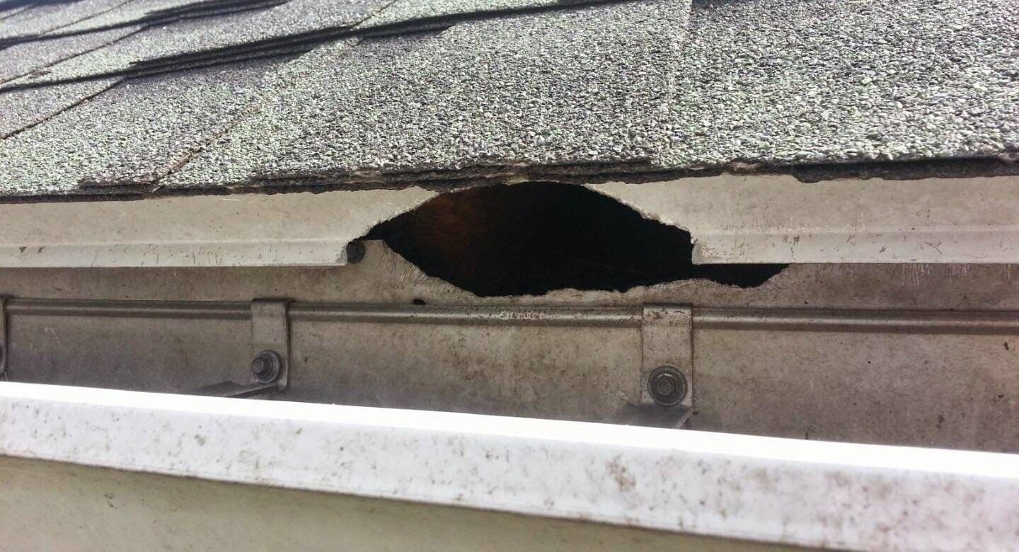
Blocked Soffit Syndrome:
Insulation blocking soffit vents represents the most common ventilation failure, eliminating intake despite adequate vent installation. Blown insulation migrates into soffit areas during installation or settling. Fiberglass batts installed tight against roof sheathing block airflow completely. Spray foam application often seals soffits inadvertently. These blockages transform functional ventilation into decorative features.
Solutions range from simple to complex depending on access and extent. Insulation baffles installed from inside maintain clearance permanently. Compressed air blown from outside clears loose insulation temporarily. Removing and reinstalling insulation correctly provides comprehensive correction. The energy efficiency standards recognize that ventilation maintenance is essential for insulation performance, justifying correction costs through energy savings.
Blockage prevention strategies:
- Install rafter baffles before insulation
- Maintain 2-inch minimum clearance
- Use rigid foam boards as barriers
- Mark soffit locations in attic
- Schedule regular inspections
Imbalance Correction Methods:
Correcting ventilation imbalances requires systematic evaluation and targeted modifications. Measuring actual installed NFA often reveals significant discrepancies from calculations. Smoke testing shows actual airflow patterns identifying dead zones. Temperature monitoring confirms whether ventilation achieves desired uniformity. These diagnostics guide specific corrections rather than wholesale replacement.
Adding intake typically proves easier than modifying exhaust systems. Supplementary soffit vents target deficient areas. Hidden vents provide additional capacity without major renovation. Gable vents converted to intake rather than exhaust improve balance. These incremental improvements achieve significant performance gains at modest cost. Professional assessment costs $500-$1,000 but prevents misdirected efforts that worsen problems.
Roe Roofing’s Ventilation Assessment and Solutions
Comprehensive Ventilation Audits
Roe Roofing performs detailed ventilation assessments that identify all contributing factors to attic moisture and temperature problems, not just obvious vent blockages. The company’s diagnostic approach uses multiple evaluation methods providing quantitative data for optimization decisions.
The assessment begins with visual inspection documenting existing ventilation components and their condition. Measurements establish actual net free areas rather than relying on assumptions. Smoke testing reveals actual airflow patterns and short circuits. Thermal imaging identifies insulation problems affecting ventilation performance. Moisture readings establish whether current ventilation adequately manages humidity. This multi-faceted evaluation costs $400-$600 but provides actionable intelligence worth thousands in prevented damage.
The company’s reports include detailed findings with photographic documentation, calculations showing required versus actual ventilation, and prioritized recommendations for improvements. Building owners receive clear explanations of problems and solutions without technical jargon. Cost estimates for recommended work enable budget planning. This transparency empowers informed decisions rather than crisis responses to ventilation failures.
Integrated Roofing and Ventilation
Roe Roofing coordinates ventilation improvements with roofing projects, maximizing value while minimizing disruption. Many ventilation upgrades prove most economical during roof replacement when access is optimal and incremental costs minimal.
The integrated approach addresses multiple issues simultaneously. Ridge vent installation during re-roofing adds only $500-$800 versus $1,500-$2,000 as standalone work. Soffit repairs coordinate with fascia replacement. Insulation baffles install easily with roof decking exposed. Bathroom fan venting corrects without additional attic access. This coordination achieves comprehensive improvements impossible with piecemeal approaches.
The company ensures all work maintains warranty compliance for both roofing and ventilation components. Manufacturer certification for integrated systems prevents finger-pointing if problems develop. Documentation satisfies insurance requirements for maintenance and upgrades. Building permits cover all work comprehensively. This attention to detail protects customer investments beyond immediate improvements.
Problem-Solving Expertise
Roe Roofing’s experience with Edmonton’s challenging climate and diverse housing stock enables creative solutions for difficult ventilation problems that standard approaches cannot resolve.
Complex rooflines with multiple levels and limited soffit areas challenge conventional ventilation strategies. The company employs alternative intake methods including smart vents that open with temperature, allowing ventilation without permanent openings. Turbine vents with thermostatically controlled dampers provide exhaust without constant heat loss. These specialized solutions cost more but solve otherwise impossible problems.
Historic homes requiring aesthetic preservation receive hidden ventilation systems maintaining architectural integrity. The company sources period-appropriate vent designs or fabricates custom solutions. Modern materials disguised with traditional appearances provide performance without visual compromise. These solutions satisfy heritage requirements while preventing moisture damage that destroys historic fabric.
Maintenance and Monitoring Programs
Roe Roofing offers ongoing maintenance programs that preserve ventilation effectiveness through regular inspection and cleaning. These programs prevent the gradual degradation that transforms functional systems into moisture traps.
Annual inspections identify developing problems before damage occurs. Soffit cleaning removes debris accumulation that reduces airflow. Exhaust vent screens clear of obstructions. Insulation migration gets corrected before complete blockage. Minor repairs prevent major failures. Documentation maintains warranty and insurance compliance. These services cost $200-$400 annually but prevent thousands in moisture damage.
The company provides monitoring solutions for critical applications. Wireless sensors track temperature and humidity, alerting to ventilation problems. Data logging establishes patterns identifying intermittent issues. Remote access enables diagnosis without site visits. These technologies provide peace of mind for vacation properties or rental units where problems might otherwise go unnoticed until severe damage occurs.
Edmonton homes require minimum 1 square foot of net free ventilation area per 150 square feet of attic floor space, split equally between soffit intake and ridge/roof exhaust, though 1:100 ratios provide superior moisture management in our extreme climate. For a typical 1,500 square foot bungalow, this means 10 square feet (1,440 square inches) total NFA, with 720 square inches at soffits, equivalent to 60-80 linear feet of continuous vented soffit or 25-30 individual 4×16-inch vents. The ventilation requirements specify these calculations use net free area after screen reductions, meaning gross vent area must be double advertised NFA to achieve actual required airflow.
Excessive ventilation is possible but rare, with problems occurring when exhaust significantly exceeds intake (creating negative pressure that pulls conditioned air from living spaces) or when total ventilation exceeds 1:50 ratios in extremely cold climates, potentially overcooling attics and increasing heating costs. However, most Edmonton homes suffer from insufficient rather than excessive ventilation, with balanced systems at 1:150 to 1:100 providing optimal moisture management without energy penalties. The building science research indicates that balanced ventilation up to 1:75 improves performance without negative consequences, making over-ventilation concerns largely theoretical for residential applications.
Vented soffits that appear functional often fail due to insulation blocking airflow (the most common cause), paint or dirt clogging perforations, insufficient total vent area despite visible vents, or imbalanced systems where inadequate exhaust prevents intake from functioning. Professional inspection costing $400-$600 identifies specific failures, revealing that 70% of “ventilated” attics have blocked or non-functional soffit vents that provide zero actual airflow despite appearing adequate from outside, making physical verification essential for diagnosing moisture problems.
Power vents create more problems than they solve for most applications, causing excessive energy loss by pulling conditioned air from living spaces, short-circuiting natural ventilation patterns, failing during power outages when ventilation is critical, and increasing operating costs by $100-$300 annually. Passive ventilation using properly balanced soffit intake and ridge exhaust provides superior year-round performance without operating costs or mechanical failures, with the energy efficiency standards showing that powered ventilation increases heating costs by 5-8% while providing minimal moisture management benefits compared to proper passive systems.
Functional soffit ventilation shows several indicators including absence of frost on attic roof decking during winter, consistent attic temperatures within 5°C of outside conditions, lack of moisture stains or mold in attic spaces, uniform snow melt patterns without ice dams, and feeling airflow at exhaust vents on calm days. Simple smoke tests using incense at soffit vents show whether air actually enters and flows toward exhaust points, while professional thermal imaging for $200-$300 provides definitive verification of airflow patterns and identifies dead zones requiring correction, with annual inspection catching problems before expensive damage occurs.