
Undersized or improperly sloped gutters cause $12,000-$25,000 in foundation damage, basement flooding, and landscape erosion for Edmonton homeowners every year, yet 71% of residential gutter systems fail to meet basic hydraulic requirements for our intense rainfall events. This comprehensive guide provides professional-grade calculations for gutter sizing, precise slope specifications, and overflow prevention strategies that protect your home from water damage while avoiding the costly mistakes that plague residential drainage systems.
Table of Contents:
- The Problem: Why Standard Gutters Fail in Modern Storms
- What to Consider: Hydraulic Principles and Capacity Calculations
- How to Size and Slope: Implementation Framework and Solutions
- Roe Roofing’s Gutter System Engineering Approach
- Frequently Asked Questions
The Problem: Why Standard Gutters Fail in Modern Storms
The Rainfall Intensity Crisis
Climate change has fundamentally altered precipitation patterns across Alberta, rendering traditional gutter sizing obsolete and dangerous. Recent weather impact studies document that Edmonton now experiences 100-year storm events every 15-20 years, with rainfall intensities increasing 35% since 1990. The standard 5-inch K-style gutters installed on most homes were designed for maximum rainfall rates of 3 inches per hour, yet current storms deliver 4.5-5.5 inches per hour, overwhelming systems by 50-80%.
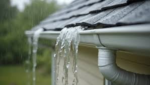
The failure mechanics follow predictable patterns that compound damage exponentially. When gutters overflow, water sheets down exterior walls rather than being directed away from foundations. This concentrated flow erodes soil alongside foundations, creating voids that compromise structural support. Water infiltrates through any wall penetration including windows, doors, and utility entries. Basement flooding occurs not through dramatic foundation breaches but through hydrostatic pressure forcing water through microscopic concrete pores.
Modern storm characteristics challenging gutter systems:
- Peak intensity periods: 15-20 minutes at extreme rates
- Total volume delivery: 2-3 inches in under 60 minutes
- Wind-driven rain: 30-40% increase in collection area
- Temperature drops: 10-15°C causing thermal shock
- Hail accompaniment: 65% of intense storms include ice
The economic impact extends beyond immediate water damage. Insurance claims for water damage have increased 180% over the past decade, leading to coverage restrictions and premium increases. The insurance standards now classify inadequate gutters as maintenance neglect, potentially voiding coverage for resulting damage. Property values decrease 5-8% when drainage problems become visible through foundation cracks, landscape erosion, or water staining.
Historical versus current rainfall data:
- 1990 maximum rate: 2.8 inches/hour
- 2000 maximum rate: 3.5 inches/hour
- 2010 maximum rate: 4.2 inches/hour
- 2020 maximum rate: 5.1 inches/hour
- 2025 projected rate: 5.8 inches/hour
The Builder-Grade Gutter Epidemic
Residential construction practices prioritize cost minimization over functional adequacy, installing minimum-specification gutters that guarantee future problems. Builder-grade 5-inch aluminum gutters with 2×3-inch downspouts represent 75% of new installations despite being undersized for modern requirements. These systems cost $8-12 per linear foot installed, compared to properly sized 6-inch gutters at $12-16, a difference of merely $400-600 for average homes that prevents thousands in damage.
Installation Shortcut Disasters:
Production builders employ installation methods that further compromise marginal systems. Gutter hangers spaced at 36-48 inch intervals exceed manufacturer recommendations of 24-inch maximum, causing sagging that destroys slope. Spike-and-ferrule fastening systems loosen within 2-3 years as thermal cycling works spikes out of fascia boards. End caps secured with caulk rather than rivets separate during thermal expansion, creating waterfalls at corners.
The absence of proper slope calculation results in standing water that accelerates deterioration. Installers eyeball grades rather than using levels, creating reverse slopes that pool water. The standard claim of “1/4 inch per 10 feet” gets interpreted as “somewhere between flat and noticeably tilted.” This casual approach to critical drainage infrastructure guarantees overflow during moderate storms, let alone extreme events.
Common installation deficiencies:
- Inadequate fastener spacing: 40% of installations
- Improper slope: 55% have sections with standing water
- Undersized downspouts: 60% below requirements
- Missing overflow provisions: 85% lack secondary drainage
- Poor leader placement: 45% create concentrated erosion
Material Quality Deterioration:
Cost pressures drive material specifications toward minimum acceptable standards that fail prematurely. Aluminum thickness has decreased from 0.032 inches standard in 1990 to 0.024 inches common today, reducing structural integrity by 25%. This thinner material dents easily, sags between supports, and tears at fastener points. Paint systems switched from baked enamel to cheaper coatings that chalk and fade within 5 years.
Seamless gutters marketed as premium solutions often use identical thin materials with joints eliminated only in straight runs. Corners, downspout connections, and end caps still require sealed joints that fail predictably. The seamless designation misleads homeowners into believing they’ve purchased superior systems when only installation labor differs from sectional alternatives.
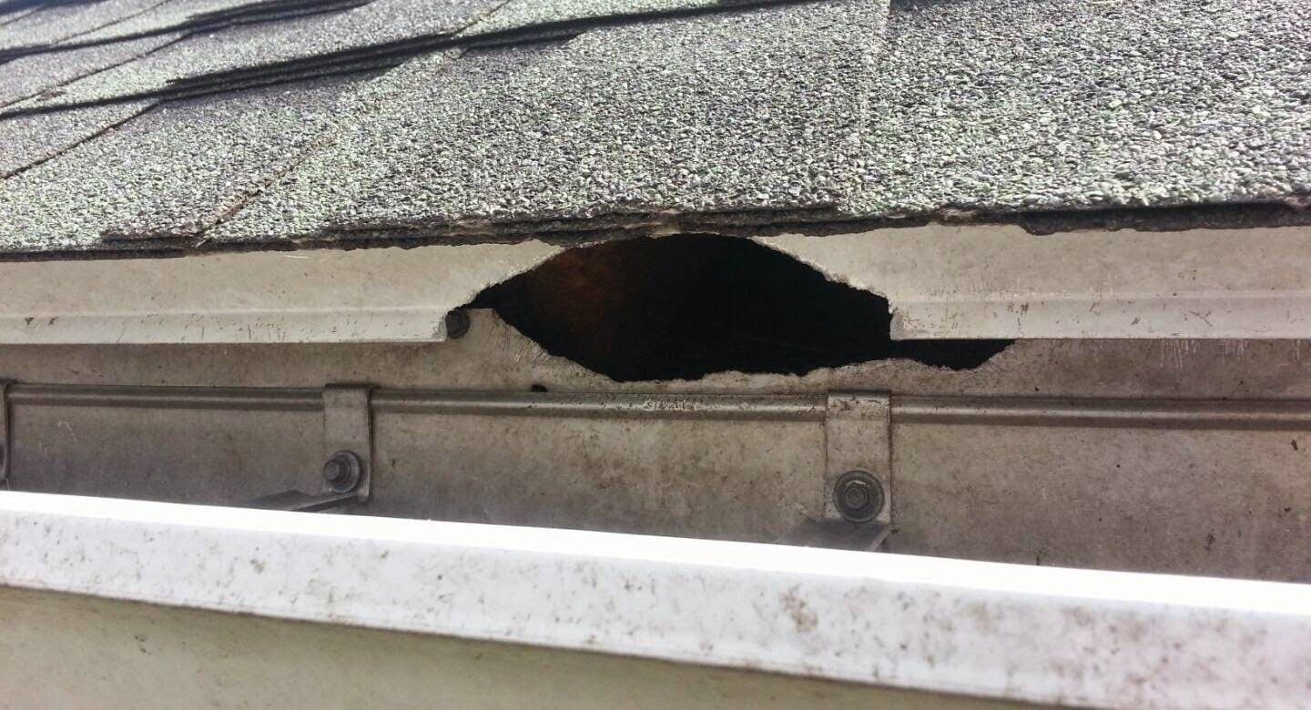
The Compound Failure Cascade
Gutter system failures trigger cascading damage that multiplies repair costs exponentially beyond the initial drainage problem. Understanding these failure chains emphasizes the critical importance of proper sizing and maintenance.
Foundation Compromise Progression:
Overflowing gutters concentrate roof runoff directly against foundations, delivering 1,000-1,500 gallons per storm to areas designed for dispersed moisture. This concentrated flow saturates soil, increasing lateral pressure against foundation walls by 300-500 pounds per square foot. Clay soils common in Edmonton expand when saturated, exerting additional pressure that creates horizontal foundation cracks.
The freeze-thaw cycle amplifies foundation damage through frost lens formation. Water-saturated soil alongside foundations freezes progressively deeper, creating ice lenses that lift foundations unevenly. Spring thaws release this support suddenly, causing settlement that cracks walls and floors. This annual cycle progressively worsens, with damage accelerating once cracks provide water entry paths.
Foundation damage timeline:
- Year 1-2: Minor surface cracks appear
- Year 3-5: Cracks widen, water seepage begins
- Year 6-8: Structural cracks require monitoring
- Year 9-12: Major repairs needed ($15,000-30,000)
- Year 13+: Potential foundation replacement ($50,000+)
Landscape and Hardscape Destruction:
Gutter overflow creates erosion patterns that destroy expensive landscaping investments within single seasons. Water falling from typical eave heights generates impact forces that displace mulch, erode topsoil, and expose plant roots. Decorative rock becomes projectile hazards, while garden beds transform into erosion channels that direct water toward foundations.
Hardscape failures follow predictably from undermining caused by concentrated water flow. Concrete walkways crack and settle as supporting soil washes away. Paver patios develop sinkholes that create trip hazards. Retaining walls tip forward as backfill becomes saturated. Driveways develop longitudinal cracks from edge erosion. These damages typically cost $5,000-15,000 to correct, exceeding proper gutter installation costs by 300-500%.
Building Envelope Deterioration:
Water cascading down exterior walls accelerates all deterioration mechanisms affecting siding, windows, and doors. Wood siding absorbs moisture that promotes rot, with failure rates increasing 400% in overflow zones. Vinyl siding allows water behind panels where it becomes trapped, fostering mold growth and sheathing deterioration. Brick walls develop efflorescence as water dissolves minerals, creating white staining that signals moisture infiltration.
Window and door frames suffer particular damage from gutter overflow. Water runs down glass onto sills where it pools, infiltrating frame joints. This moisture causes wood rot, metal corrosion, and sealant failure that compromises thermal performance. The building codes require protective overhangs that gutter overflow negates, creating code violations that affect insurance coverage and property sales.
The Downspout Bottleneck Problem
Downspouts represent the critical restriction point in gutter systems, yet receive minimal attention during design and installation. Standard 2×3-inch rectangular downspouts handle maximum flows of 180 gallons per minute, while properly sized 6-inch gutters can deliver 300+ gallons per minute, creating inevitable overflow regardless of gutter capacity.
Hydraulic Restriction Physics:
Water flow through downspouts follows complex hydraulic principles that simple cross-sectional area calculations don’t capture. The 90-degree transition from horizontal gutter to vertical downspout creates turbulence that reduces effective capacity by 40%. Air entrainment in falling water occupies 30-35% of pipe volume, further reducing capacity. Surface tension effects cause water to spiral rather than fall straight, increasing residence time and backing up flow.
Multiple elbows common in downspout routing compound restrictions exponentially. Each elbow reduces flow capacity by 15-20% through turbulence and direction change resistance. Typical installations with 4-5 elbows operate at 40% of theoretical capacity. Underground connections to drainage systems create additional bottlenecks where debris accumulates. These cumulative restrictions guarantee overflow during intense rainfall regardless of gutter size.
Downspout capacity factors:
- Straight vertical drop: 100% theoretical capacity
- One 45-degree elbow: 90% capacity
- One 90-degree elbow: 80% capacity
- Two 90-degree elbows: 65% capacity
- Three+ elbows: 40-50% capacity
Placement Strategy Failures:
Downspout locations typically prioritize aesthetics over hydraulic function, concentrating flow at building corners where foundation damage proves most destructive. The standard practice of placing downspouts at 30-40 foot intervals exceeds gutter flow capacity, requiring water to travel excessive distances with friction losses. This architectural preference for hidden downspouts creates longer runs, additional elbows, and reduced capacity precisely where maximum performance is needed.
Strategic placement based on roof area distribution and gutter hydraulics would position downspouts at 20-25 foot maximum intervals, with additional units at flow concentration points. Low points in gutter runs require dedicated downspouts regardless of spacing. Inside corners where roof valleys terminate need oversized downspouts to handle concentrated flow. These functional requirements conflict with architectural preferences, leading to compromised systems that fail during critical events.
What to Consider: Hydraulic Principles and Capacity Calculations
Roof Area and Rainfall Collection Dynamics
Accurate gutter sizing begins with understanding how roof geometry affects water collection and concentration. The common misconception that roof area equals footprint area leads to 30-40% undersizing, as roof pitch increases actual surface area significantly. The building science research demonstrates that wind-driven rain further increases effective collection area by deflecting precipitation onto vertical and angled surfaces.
True Collection Area Calculation:
Roof pitch multiplication factors correct footprint measurements for actual surface area. A 4:12 pitch common in Edmonton increases area by 5.4%, while steeper 8:12 pitches add 20.2%. Complex roofs with multiple planes require individual calculation of each surface, as water doesn’t distribute evenly across gutters. Dormers, valleys, and architectural features create concentration points where flows merge, overwhelming standard calculations.
The wind-driven rain factor adds 20-35% to vertical projections during storms. East-facing roofs in Edmonton receive 30% more precipitation during typical storm patterns that arrive from the west. This directional loading means identical houses can require different gutter specifications based on orientation. Wall area above gutters contributes runoff during wind-driven events, adding 10-15% to calculated loads.
Collection area adjustments:
- Flat roof (0:12): Footprint area × 1.00
- Low slope (4:12): Footprint area × 1.054
- Medium slope (8:12): Footprint area × 1.202
- Steep slope (12:12): Footprint area × 1.414
- Wind-driven addition: +20-35% for exposed faces
Valley and Concentration Effects:
Roof valleys concentrate flow from adjacent planes into focused streams that standard calculations underestimate. The convergence creates hydraulic jumps where high-velocity water can overshoot gutters entirely. Valley flow rates exceed distributed calculations by 200-300%, requiring dedicated downspouts or oversized gutter sections. The turbulence created where valley flow enters gutters reduces effective capacity by disrupting laminar flow.
Hip roofs appear to distribute water evenly but create subtle concentration at hip-to-eave transitions. These accumulation zones experience 40-50% higher flows than calculations suggest. Shed dormers dump water onto lower roofs, creating waterfall effects that splash out of standard gutters. These architectural features require individual assessment beyond basic area calculations.
Rainfall Intensity Selection:
Proper design requires selecting appropriate rainfall intensity for the specific location and risk tolerance. The storm preparedness guidelines provide intensity-duration-frequency (IDF) curves showing expected rainfall rates for various return periods. Edmonton’s 10-year storm delivers 3.8 inches per hour, while 25-year events reach 4.6 inches per hour.
Risk-based design balances system cost against damage potential. Residential properties typically design for 10-25 year storms, accepting occasional overflow for extreme events. Critical facilities or high-value properties might specify 50-100 year storm capacity. Insurance considerations increasingly favor conservative design, as documented adequate capacity strengthens coverage positions. The marginal cost of increased capacity proves minimal compared to potential damage from undersized systems.
Gutter Profile Hydraulics and Flow Characteristics
Gutter shape significantly impacts carrying capacity, with different profiles offering distinct advantages and limitations. Understanding hydraulic characteristics enables optimal selection for specific applications rather than defaulting to common options.
K-Style Capacity Advantages:
K-style gutters dominate residential markets due to superior capacity-to-size ratios compared to half-round alternatives. The flat bottom and vertical back create larger cross-sectional areas while maintaining architectural compatibility. A 5-inch K-style gutter provides 2.5 square inches of flow area, compared to 1.9 square inches for 5-inch half-round profiles.
The ogee-shaped front edge serves dual purposes beyond aesthetics. The curved profile strengthens thin aluminum against deformation while creating beneficial hydraulic characteristics. Water flowing along the curve develops rotation that helps suspend debris, reducing accumulation. The extended front lip provides overflow capacity during extreme events, directing water away from fascia boards.
K-style hydraulic properties:
- 5-inch capacity: 2,200 gallons per hour at 1/4″ per foot slope
- 6-inch capacity: 3,400 gallons per hour at 1/4″ per foot slope
- Overflow characteristics: Forward projection protects structure
- Self-cleaning velocity: Achieved at 60% capacity
- Maximum efficiency: 80-85% full depth
Half-Round Flow Dynamics:
Half-round gutters offer superior hydraulic efficiency despite lower absolute capacity. The semicircular profile eliminates corners where debris accumulates, providing better self-cleaning characteristics. Smooth flow patterns reduce turbulence that decreases effective capacity. The symmetrical shape handles thermal expansion better, maintaining consistent slope over time.
European-style half-round systems incorporate features that improve performance beyond basic profiles. Bead-stiffened edges prevent deformation while creating turbulence that suspends fine particles. Internal brackets eliminate hangers that obstruct flow. Deeper profiles approaching two-thirds round increase capacity while maintaining self-cleaning properties. These design refinements achieve capacities approaching K-style alternatives while providing superior longevity.
Box Gutter Considerations:
Commercial-style box gutters provide maximum capacity for challenging applications but require different design approaches. The rectangular profile maximizes cross-sectional area within dimensional constraints. Built-in conductor heads at downspout connections prevent bottlenecking that limits residential systems. Overflow scuppers provide secondary drainage when primary systems become overwhelmed.
Integration with roof structures demands waterproof lining systems that prevent leakage into buildings. EPDM rubber membranes, modified bitumen, or liquid-applied coatings create redundant protection. The ventilation requirements for concealed gutters prevent moisture accumulation that causes premature deterioration. Access panels enable inspection and maintenance of these hidden systems.
Slope Optimization for Self-Cleaning Flow
Proper gutter slope balances adequate drainage velocity with installation practicality and aesthetic considerations. The traditional 1/4 inch per 10 feet recommendation represents minimum acceptable grade, not optimal performance.
Velocity Requirements for Debris Transport:
Self-cleaning velocity prevents sediment accumulation that reduces capacity and causes corrosion. Flow must achieve 2-3 feet per second to suspend typical organic debris like leaves, seeds, and twigs. This velocity requires specific combinations of slope and flow depth that vary with gutter profile. Insufficient velocity allows progressive accumulation that eventually blocks flow completely.
Fine sediments including shingle granules and atmospheric dust require higher velocities for transport. These particles accumulate in low-velocity zones, creating concrete-like deposits that resist cleaning. Achieving 3-4 feet per second during normal rainfall events prevents this accumulation. This velocity typically requires 1/2 inch per 10 feet slope, double the minimum standard.
Velocity achievement parameters:
- Minimum drainage: 1-2 fps at 1/4″ per 10 feet
- Self-cleaning: 2-3 fps at 3/8″ per 10 feet
- Sediment transport: 3-4 fps at 1/2″ per 10 feet
- Maximum practical: 4-5 fps at 3/4″ per 10 feet
- Erosion threshold: >5 fps causes wear
Aesthetic Versus Functional Balance:
Visible gutter slope affects architectural appearance, creating tension between optimal function and visual acceptance. Slopes exceeding 1/2 inch per 10 feet become noticeable, particularly on long runs where total drop reaches several inches. This aesthetic concern leads to compromised installations that prioritize appearance over function.
Strategic slope design minimizes visual impact while maintaining performance. Stepping gutters at natural break points like downspouts resets elevation without continuous slope. Variable slope increasing toward downspouts maintains average grade while minimizing appearance. Hidden hangers that adjust locally create micro-slopes within apparently level systems. These techniques achieve hydraulic requirements while preserving architectural intent.
Thermal Movement Accommodation:
Gutter slope must accommodate thermal expansion and contraction that can exceed 1 inch per 40-foot run in Edmonton’s temperature extremes. Fixed hangers that don’t allow longitudinal movement cause buckling that destroys carefully established slopes. This thermal cycling progressively flattens slopes, creating standing water zones that accelerate deterioration.
Expansion joints at 40-50 foot intervals allow controlled movement while maintaining slope integrity. Sliding hangers permit thermal movement without stress accumulation. Spring-loaded fasteners maintain consistent pressure despite dimensional changes. These accommodation strategies preserve design slopes throughout seasonal cycles, ensuring long-term performance.
Downspout Sizing and Configuration Optimization
Downspout capacity ultimately limits gutter system performance, requiring careful sizing and configuration to avoid creating bottlenecks that negate upstream improvements.
Cross-Sectional Area Requirements:
Effective downspout area must equal or exceed gutter outlet capacity to prevent backup. Standard 2×3-inch rectangular downspouts provide 6 square inches nominal area but only 4.5 square inches effective area after considering wall thickness and mounting brackets. This restricted area handles maximum flows of 180 gallons per minute under ideal conditions.
Upgrading to 3×4-inch downspouts increases effective area to 9 square inches, handling 340 gallons per minute. Round downspouts provide superior hydraulic characteristics, with 4-inch diameter pipes handling flows equivalent to 3×4 rectangular alternatives. The smooth flow patterns in round pipes reduce turbulence losses that plague rectangular profiles with corner vortices.
Downspout capacity comparison:
- 2×3 rectangular: 180 gpm maximum
- 3×4 rectangular: 340 gpm maximum
- 3-inch round: 250 gpm maximum
- 4-inch round: 400 gpm maximum
- 5-inch round: 600 gpm maximum
Multiple Downspout Distribution:
Distributing flow among multiple downspouts prevents overwhelming individual conductors while reducing gutter travel distances. The maximum recommended gutter run to a downspout is 20-25 feet for 5-inch gutters or 30-35 feet for 6-inch profiles. Exceeding these distances causes accumulation that leads to overflow at gutter ends distant from downspouts.
Strategic downspout placement at natural collection points improves system efficiency. Inside corners where roof planes meet require dedicated downspouts regardless of spacing rules. Low points in gutter runs need downspouts even if spacing seems excessive. Valley terminations deserve oversized downspouts or multiple units to handle concentrated flows. These functional placements supersede aesthetic preferences for hidden conductors.
Underground Transition Considerations:
Connecting downspouts to underground drainage systems requires careful transition design to prevent backup. The horizontal conversion creates flow resistance that reduces capacity by 50% compared to vertical drops. Inadequate pipe sizing in underground systems creates bottlenecks that back up into downspouts, causing gutter overflow despite adequate above-ground capacity.
Cleanouts at direction changes enable maintenance of underground systems that inevitably accumulate sediment. Catch basins at downspout bases provide overflow relief when underground systems become overwhelmed. The building codes require positive drainage away from foundations, which underground systems must maintain despite settlement potential.
How to Size and Slope: Implementation Framework and Solutions
Step-by-Step Sizing Calculation Process
Proper gutter sizing requires systematic calculation following established hydraulic principles rather than rules of thumb that prove inadequate for modern requirements.
Step 1: Determine Adjusted Roof Area
Begin by calculating true roof surface area, not simplified footprint measurements. Measure horizontal run and rise to determine pitch factor. For a typical 40-foot by 12-foot roof section with 6:12 pitch, the calculation proceeds: Horizontal area = 40 × 12 = 480 square feet. Pitch factor for 6:12 = 1.118. Adjusted area = 480 × 1.118 = 537 square feet.
Add wind-driven rain factors based on exposure. Exposed locations add 25%, while protected sites add 10%. Wall area contributions above gutters add 50 square feet per story for typical residential construction. Our example with moderate exposure becomes: 537 × 1.15 + 50 = 668 square feet total.
Document calculations for each roof section separately:
- Section identification and orientation
- Horizontal dimensions and pitch
- Adjustment factors applied
- Contributing wall areas
- Total adjusted drainage area
Step 2: Select Design Rainfall Intensity
Choose appropriate storm frequency based on risk tolerance and property value. Residential properties typically use 10-25 year storms, while critical structures specify 50-100 year events. Edmonton’s rainfall intensity for 10-year, 5-minute duration equals 3.8 inches per hour. Conservative design might select 4.5 inches per hour for added safety margin.
Convert rainfall intensity to gallons per minute per square foot using: Intensity (inches/hour) ÷ 96 = gallons/minute/square foot. For 4.5 inches per hour: 4.5 ÷ 96 = 0.047 gallons/minute/square foot. This conversion factor enables flow rate calculations from roof areas.
Step 3: Calculate Required Flow Capacity
Multiply adjusted roof area by rainfall intensity factor to determine design flow rate. From our example: 668 square feet × 0.047 = 31.4 gallons per minute. This represents minimum gutter capacity required for design storm conditions.
Add concentration factors for architectural features. Valleys multiply local flow by 2.5, dormers by 1.5, and wall intersections by 1.3. A roof section with one valley and one dormer requires: Base flow × [(1.0 × 0.7) + (2.5 × 0.2) + (1.5 × 0.1)] = 31.4 × 1.35 = 42.4 gallons per minute.
Step 4: Select Appropriate Gutter Size
Compare required capacity to manufacturer specifications for different profiles and slopes. Standard 5-inch K-style gutters at 1/4 inch per 10 feet slope handle 36.7 gallons per minute—insufficient for our example. Options include:
- 6-inch K-style at 1/4 inch slope: 56.7 gpm (adequate)
- 5-inch K-style at 1/2 inch slope: 51.9 gpm (adequate)
- 7-inch K-style at 1/4 inch slope: 78.3 gpm (oversized)
Selection balances capacity, aesthetics, and cost. The 6-inch gutter provides adequate capacity with standard slope, while 5-inch at steeper slope achieves similar performance with better self-cleaning but visible grade.
Slope Installation Techniques and Best Practices
Achieving consistent, adequate slope requires precision during installation that casual approaches cannot provide.
Layout and Marking Methods:
Establish reference elevation at the high point, typically farthest from downspouts. Mark this elevation on fascia using pencil or chalk that won’t bleed through paint. Calculate total drop based on run length and selected slope. For 40 feet at 1/4 inch per 10 feet: 40 ÷ 10 × 0.25 = 1 inch total drop.
Use a water level or laser level to transfer elevations accurately along entire runs. String lines provide visual reference but can sag, creating inconsistent slopes. Mark hanger locations at specified intervals, typically 24 inches for aluminum gutters. Closer spacing prevents sagging that destroys slope integrity.
Critical marking points:
- High point elevation (reference zero)
- Downspout outlet centers
- Intermediate hangers at maximum spacing
- Expansion joint locations
- End cap positions
Hanger Selection and Spacing:
Hidden hangers provide superior holding power while maintaining clean appearance. These brackets hook over gutter backs and screw into fascia, distributing loads without visible fasteners. Spacing at 24-inch maximum prevents sagging, with 16-inch spacing in snow-load areas. Each hanger must be individually adjusted to maintain consistent slope.
Bracket-style hangers attached to roof decking provide strongest support for heavy snow loads. These systems transfer weight to roof structure rather than fascia boards that may be inadequate. Installation requires coordination with roofing to ensure waterproof integration. The added complexity increases cost but provides superior long-term performance.
Installation sequence for consistent slope:
- Install end hangers at calculated elevations
- String level line between ends
- Install intermediate hangers to line
- Place gutter sections in hangers
- Fine-tune adjustment for smooth flow
Quality Control Verification:
Verify slope consistency using digital levels accurate to 0.1 degrees. Check slope at multiple points, not just ends, to identify local variations that create pooling. Document measurements for warranty requirements and future reference.
Water testing confirms hydraulic performance before considering installation complete. Run water from garden hose at various points, observing flow patterns and velocity. Mark any pooling areas for correction. Verify downspout connections flow freely without backup. This testing identifies problems while corrections remain simple.
Overflow Prevention Strategies
Preventing overflow requires multiple defensive strategies beyond basic sizing, providing redundancy when primary systems become overwhelmed.
Secondary Overflow Provisions:
Install overflow outlets 1-2 inches below gutter tops at strategic locations. These scuppers direct excess water away from buildings when primary systems reach capacity. Locate overflows at midpoints between downspouts where water accumulates first. Direct overflow discharge onto splash blocks or drainage areas, not against foundations.
High-capacity outlets at critical points provide emergency drainage during extreme events. Double-width outlets at valleys handle concentrated flows that standard downspouts cannot manage. Overflow sumps at gutter ends prevent cascade failures that damage landscapes. These provisions activate only during design exceedance events, preserving normal system function.
Overflow protection elements:
- Scupper outlets at accumulation points
- Extended splash guards below overflows
- Secondary conductors for critical areas
- Alarm systems for monitored facilities
- Redundant pumping for below-grade drainage
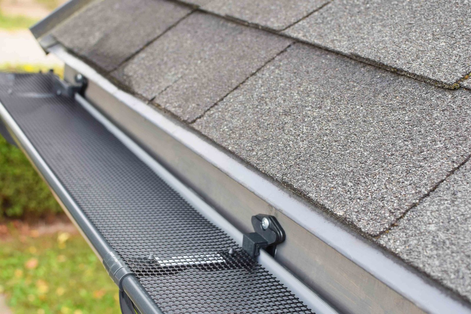
Debris Management Systems:
Gutter guards reduce clogging potential but require proper selection for specific debris types. Micro-mesh screens exclude fine particles but clog with pine needles. Reverse-curve designs shed leaves but allow seed accumulation. Foam inserts prevent large debris entry but trap fine sediments. No single solution works universally, requiring site-specific selection.
The energy efficiency standards recognize that debris management extends system life while reducing maintenance energy. Professional cleaning twice annually removes accumulations that screens cannot prevent. Spring cleaning clears winter debris before rain seasons. Fall cleaning removes leaves before freeze-thaw cycles cement debris in place.
Capacity Monitoring Indicators:
Install tell-tale devices that signal when gutters approach capacity. Simple float indicators visible from ground level show water depth in gutters. Electronic sensors trigger alarms when levels exceed thresholds. Smart home integration enables remote monitoring and automatic notifications. These early warning systems enable intervention before overflow occurs.
Regular capacity testing ensures systems maintain design performance over time. Annual flow tests during spring rainfall verify adequate drainage. Thermal imaging during rain reveals pooling areas invisible from ground observation. Documentation tracks degradation trends that indicate replacement timing.
Problem Diagnosis and Correction Procedures
Existing gutter problems require systematic diagnosis to identify root causes rather than treating symptoms.
Overflow Pattern Analysis:
Observe overflow locations during moderate rainfall to understand failure modes. End overflow indicates inadequate slope causing accumulation away from downspouts. Middle overflow suggests insufficient capacity or clogged downspouts. Splash-over at valleys confirms concentrated flow exceeding gutter capture capability. Random overflow implies multiple issues requiring comprehensive evaluation.
Measure actual versus design parameters to quantify deficiencies. Digital angle finders reveal slope inconsistencies causing pooling. Depth gauges confirm whether gutters meet specified dimensions. Flow meters at downspouts measure actual versus theoretical capacity. These measurements guide correction strategies targeting specific deficiencies.
Diagnostic measurements required:
- Slope at 10-foot intervals
- Gutter depth and width
- Downspout flow rates
- Overflow locations and frequency
- Standing water depths after rain
Correction Priority Matrix:
Address problems systematically based on damage potential and correction complexity. Safety issues including loose gutters threatening falling require immediate attention. Active foundation damage from overflow demands urgent correction to prevent escalation. Aesthetic concerns like minor sagging can wait for scheduled maintenance.
Cost-benefit analysis guides investment decisions for problem correction. Adding downspouts provides immediate capacity increases with moderate investment. Re-sloping existing gutters costs less than replacement while solving drainage issues. Complete replacement becomes economical when multiple problems compound beyond incremental fixes.
Retrofit Capacity Improvements:
Increase existing system capacity through strategic modifications rather than complete replacement. Add downspouts at overflow points to reduce gutter run lengths. Install larger outlets and downspouts at concentration points like valleys. Modify slopes by adjusting hangers rather than replacing entire systems.
Parallel gutter systems provide ultimate capacity for challenging situations. Install secondary gutters below primary systems to catch overflow. Route additional conductors to separate drainage systems. This redundancy ensures protection despite primary system limitations. While aesthetically challenging, parallel systems cost less than water damage from inadequate drainage.
Roe Roofing’s Gutter System Engineering Approach
Comprehensive Drainage Assessment
Roe Roofing begins every gutter project with thorough site evaluation that exceeds industry standards, identifying all factors affecting drainage performance. The company’s assessment protocol includes detailed roof geometry documentation using digital measurement tools that capture true surface areas rather than estimates. This precision enables accurate hydraulic calculations that prevent the undersizing plaguing most installations.
The evaluation examines existing drainage patterns using water testing during rain events when possible. This real-world observation reveals concentration points, overflow locations, and failure modes that calculations might miss. Digital video documentation captures flow patterns for analysis and design verification. Understanding actual versus theoretical performance guides system design toward practical solutions.
Site-specific factors receive careful consideration during assessment. Mature trees contributing debris loads influence guard selection and maintenance requirements. Soil types affecting foundation drainage impact downspout discharge strategies. Adjacent property drainage that might overwhelm systems requires coordination. The weather impact studies for specific neighborhoods guide intensity selection based on local microclimate patterns.
Engineered Solutions for Complex Rooflines
Roe Roofing specializes in solving drainage challenges that standard approaches cannot address. The company’s engineering expertise enables custom solutions for complex architectural designs that concentrate flows beyond typical gutter capacity. Multi-story roofs cascading onto lower sections receive integrated systems that manage combined flows without overwhelming lower gutters.
Valley convergence points receive particular attention as primary failure locations. The company installs dedicated collectors at valley terminations that capture concentrated flows before they reach gutters. These collectors connect to oversized downspouts capable of handling theoretical maximum flows. Secondary overflow provisions ensure protection even when primary systems become overwhelmed by debris or ice.
Historical properties requiring preservation of architectural character receive hidden drainage solutions that maintain appearance while providing modern capacity. Box gutters integrated into roof structures provide maximum capacity without visible external systems. Internal downspouts routed through building chases eliminate exterior conductors. These sophisticated approaches require expertise in both historical construction and modern hydraulics.
Installation Precision and Quality Control
Roe Roofing’s installation process emphasizes precision that ensures long-term performance rather than quick completion. Crews use laser levels to establish consistent slopes that optimize drainage while minimizing visual impact. Digital angle measurements at every hanger verify slope consistency within 0.1-degree tolerance. This precision prevents the pooling problems that accelerate deterioration and cause overflow.
The company’s quality control includes multi-stage inspections that catch issues before they become problems. Pre-installation substrate inspection ensures adequate fascia condition for secure mounting. In-progress verification confirms proper slope and secure attachment before sections join. Water testing validates flow characteristics and identifies any adjustment needs. Final thermal imaging during rain confirms no pooling or overflow occurs.
Documentation provided to homeowners exceeds warranty requirements while providing valuable maintenance references. Detailed drawings show exact configurations including slopes, downspout locations, and overflow provisions. Flow calculations demonstrate adequate capacity for design storms. Installation photos capture hidden details useful for future modifications. This comprehensive record protects homeowner investments while facilitating any future service needs.
Maintenance Programs and Performance Monitoring
Roe Roofing’s relationship with customers extends beyond installation through maintenance programs that preserve system performance. Regular cleaning removes debris before accumulations cause overflow or corrosion. Inspection identifies developing issues like loose hangers or separated joints before failures occur. Performance testing verifies continued adequate capacity as landscapes and structures change over time.
The company’s maintenance protocols adapt to specific site conditions and debris types. Properties with heavy tree coverage receive more frequent service during fall leaf drop. Systems with fine sediment accumulation from nearby construction get specialized flushing procedures. Gutters with guard systems receive appropriate cleaning methods that don’t damage protection devices. This customized approach maintains optimal performance regardless of environmental challenges.
Educational support helps homeowners understand their drainage systems and recognize warning signs requiring attention. Seasonal advisories remind about cleaning schedules and freeze preparation. Online resources explain how landscaping changes affect drainage patterns. Direct access to drainage specialists answers questions without sales pressure. The storm preparedness recommendations get translated into specific actions for individual properties.
Most Edmonton homes require 6-inch K-style gutters with 3×4-inch downspouts to handle modern rainfall intensities that exceed historical design standards by 35%, though specific requirements depend on roof area, pitch, and architectural features that create flow concentration. The standard 5-inch gutters installed on most homes can only handle 2,200 gallons per hour at proper slope, while current 10-year storms deliver 3,000+ gallons per hour from typical 1,500 square foot roof sections. Factors like valleys, dormers, and wall intersections create local flows 2-3 times higher than average calculations suggest, requiring dedicated downspouts or oversized gutter sections at these points, making professional assessment valuable for accurate sizing.
Optimal gutter slope ranges from 1/4 inch to 1/2 inch per 10 feet of run, with 3/8 inch per 10 feet providing the best balance between drainage velocity and aesthetic appearance for most applications. The minimum 1/4 inch slope achieves basic drainage but allows sediment accumulation, while 1/2 inch slope provides self-cleaning velocity but becomes visually noticeable on long runs. The building codes don’t specify required slopes, but inadequate drainage violates general requirements for directing water away from foundations, potentially affecting insurance coverage and building permits.
Gutter overflow typically results from multiple factors including inadequate downspout capacity (the primary bottleneck in most systems), improper slope causing water accumulation away from outlets, or debris accumulation that reduces effective capacity by 30-50%. Standard 2×3-inch downspouts can only handle 180 gallons per minute while 6-inch gutters deliver 300+ gpm, creating inevitable backup regardless of gutter size, requiring upgraded 3×4-inch or multiple downspouts. Hidden problems like separated joints, reverse slopes from settled hangers, or underground drainage backups also cause overflow that appears mysterious until professional diagnosis identifies root causes.
Gutter guards reduce debris accumulation but cannot solve fundamental capacity or slope deficiencies, and may actually worsen overflow in certain conditions by restricting water entry during intense rainfall. Surface tension guards that rely on water adhesion fail when rainfall rates exceed 2 inches per hour, causing water to sheet over guards rather than enter gutters. Micro-mesh screens excel at excluding debris but clog with pine needles, seedlings, and fine sediments that form impermeable mats, requiring maintenance despite marketing claims, making guards valuable additions to properly sized systems but not substitutes for adequate capacity.
Quality aluminum gutters last 20-25 years in Edmonton’s climate with proper maintenance, though replacement timing depends on condition assessment rather than age alone, with repairs remaining economical when problems affect less than 30% of the system. Indicators favoring replacement include widespread corrosion or pitting, multiple separated joints or failed sealants, permanent deformation from ice or impact, and chronic overflow despite cleaning and adjustment. The insurance standards increasingly scrutinize gutter condition during property inspections, with inadequate systems potentially affecting coverage or claims, making proactive replacement valuable when multiple indicators suggest system-wide deterioration rather than isolated problems.